the
Heavy Duty Bolt
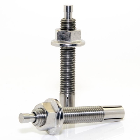
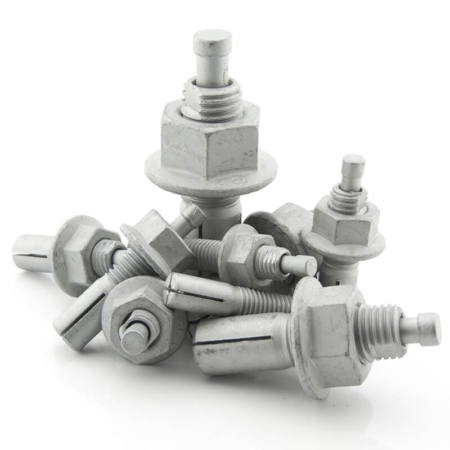
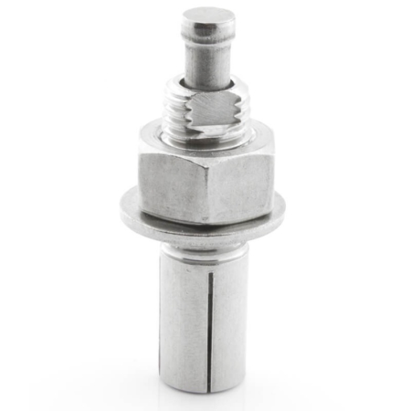
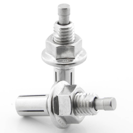
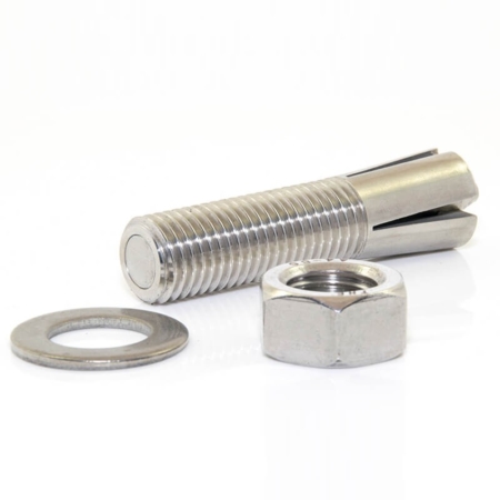
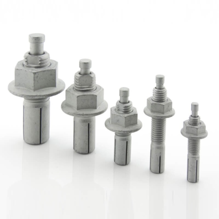
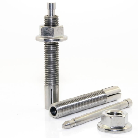
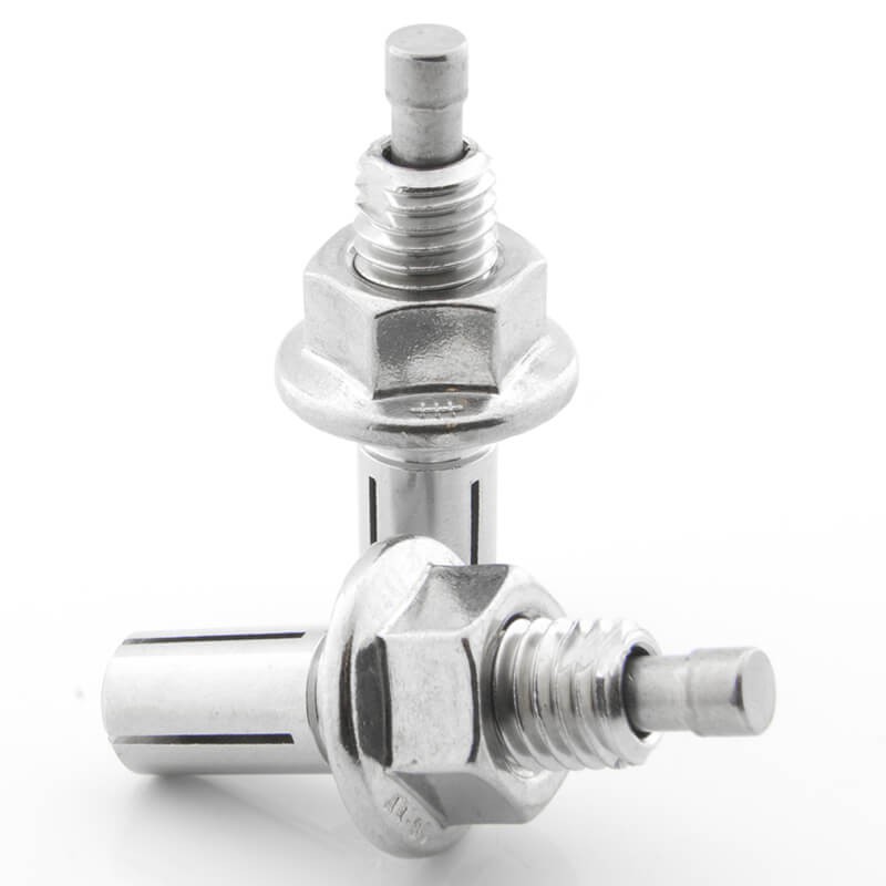
The HD, or Heavy Duty Bolt was developed to address the need for a shorter blind fixing with improved performance where a shear plane would fall across the legs of a Blind Bolt.
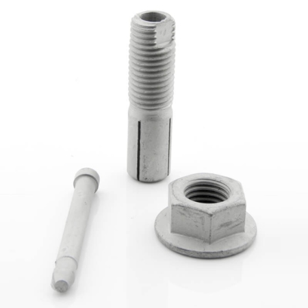
With its expanding base and unique pin locking mechanism the HD bolt is the idea fixing solution between heavy weight steel sections. The HD bolt employs a simple activation method designed to reduce installation time and expense. A hammer and a spanner are all thats required to activate the Heavy Duty Bolt removing the need for costly specialist equipment required with similar products.
- Quick and easy to install Hd2.
- No oversized hole required.
- Finished with a Zinc Flake coating giving 1000 hours salt spray protection.
- Increased assembly efficiency.
- Unique pin locking design.
Please visit our News page for information about new products and applications. Alternatively please contact us using the details below to discuss your projects and how we could help.
For detailed information on installation, please view our Heavy Duty Bolt Installation guide, Heavy Duty Bolt Fitting Instructions.
HEAVY DUTY BOLT
Technical Details
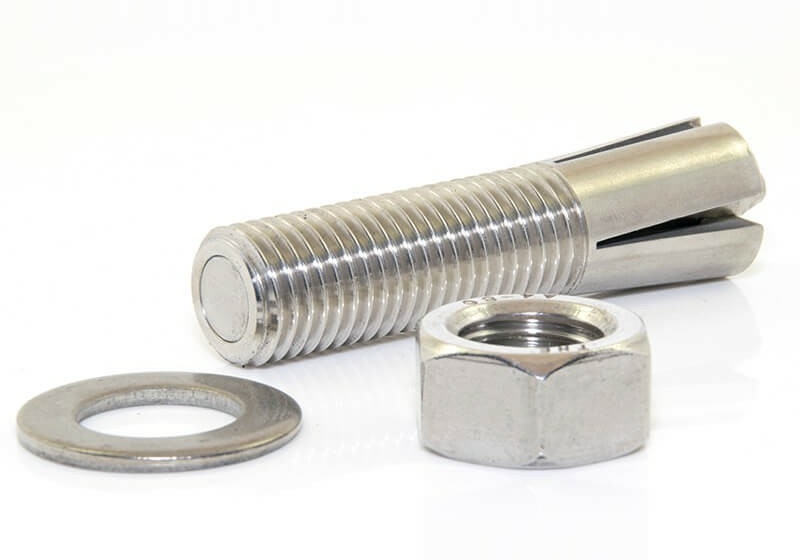
NOTE: All dimensions are in mm unless stated otherwise.
The Blind Bolt Company reserve the right to change these technical details without notice.
Heavy Duty Product Specification Zinc Flake 1000Hr SSP
|
||||||
| Product Code |
Bolt Size |
Hole Diameter | Fixing Thickness | Depth Clearance |
Corrosion Protection |
|
| Min | Max | |||||
| HD0845ZF | M8 x 45 | 8 | 7 | 25 | 10 | Zinc Flake 1000Hr |
| HD1045ZF | M10 x 45 | 10 | 7 | 25 | 12 | Zinc Flake 1000Hr |
| HD1060ZF | M10 x 60 | 10 | 7 | 40 | 12 | Zinc Flake 1000Hr |
| HD1245ZF | M12 x 45 | 12 | 8 | 22 | 15 | Zinc Flake 1000Hr |
| HD1260ZF | M12 x 60 | 12 | 8 | 34 | 15 | Zinc Flake 1000Hr |
| HD1275ZF | M12 x 75 | 12 | 8 | 48 | 15 | Zinc Flake 1000Hr |
| HD1660ZF | M16 x 60 | 16 | 12 | 30 | 25 | Zinc Flake 1000Hr |
| HD1675ZF | M16 x 75 | 16 | 12 | 45 | 25 | Zinc Flake 1000Hr |
| HD2070ZF | M20 x 70 | 20 | 15 | 32 | 30 | Zinc Flake 1000Hr |
| HD2085ZF | M20 x 85 | 20 | 15 | 47 | 30 | Zinc Flake 1000Hr |
Design Resistance for HD Type Blind Bolts Design to BS EN 1993-1-8
|
|||
| Bolt Size | Tensile (kN) | Single Shear (kN) | Recommended Pre-load Tightening Torque (Nm) |
| M8 |
8.5 |
13.6 | 20 |
| M10 | 25.2 | 21.9 | 35 |
| M12 | 46.4 | 32.2 | 45 |
| M16 | 57.5 | 60.8 | 95 |
| M20 | 77.5 | 95.5 | 120 |
Important Note
The above resistances are equally appropriate for designs to BS 5950
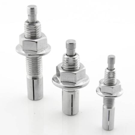
Stainless Steel HD Bolts
Heavy Duty Product Specification A4-70 STAINLESS STEEL |
|||||
| Product Code |
Bolt Size |
Hole Diameter | Fixing Thickness | Depth Clearance | |
| Min | Max | ||||
| HD0845SS | M8 x 45 | 8 | 7 | 25 | 10 |
| HD1045SS | M10 x 45 | 10 | 7 | 25 | 12 |
| HD1060SS | M10 x 60 | 10 | 7 | 40 | 12 |
| HD1245SS | M12 x 45 | 12 | 8 | 22 | 15 |
| HD1260SS | M12 x 60 | 12 | 8 | 37 | 15 |
| HD1660SS | M16 x 60 | 16 | 12 | 30 | 25 |
| HD2070SS | M20 x 70 | 20 | 15 | 32 | 30 |
Design Resistance for HD Type Blind Bolts
|
|||
| Bolt Size | Tensile (kN) | Shear (kN) | Recommended Pre-load Tightening Torque (Nm) |
| M8 |
10.5 |
11.5 | 18 |
| M10 | 20.2 | 18.4 | 24 |
| M12 | 31.4 | 27.1 | 30 |
| M16 | 40.1 | 51.1 | 45 |
| M20 | 68.7 | 80.2 | 80 |
Important Note
The above resistances are equally appropriate for designs to BS 5950
HEAVY DUTY BOLT
Testing Data Explained
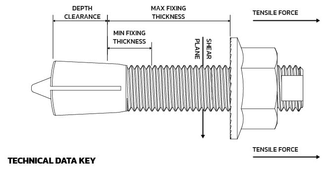
These dimensions are outlined below, please use the menu above the picture to isolate each dimension and testing term to view a brief description. However, if there is anything that you are unsure about please feel free to contact us on the number at the top of your screen or send us an e-mail.
Due to the unique properties of the HD Bolt there are certain operation criteria that must be met to ensure its successful application.
Use the menu to see an explanation of the testing criteria found on our technical data sheets. However, if there is anything that you are unsure about please feel free to contact us on the number below or click here to send us an e-mail.
HEAVY DUTY BOLT
Fitting Instructions
The following videos visually represents the detailed installation of the Heavy Duty Bolt.
HD Bolt Installation Instruction

