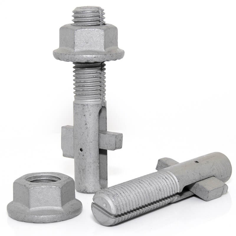
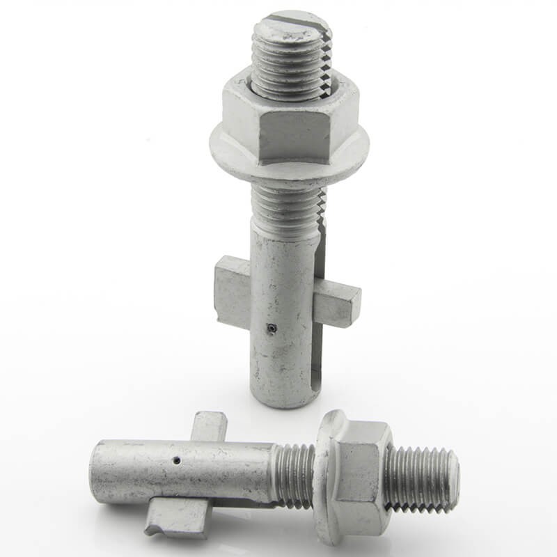
Find Your Standard Blind Bolt
Input the overall thickness

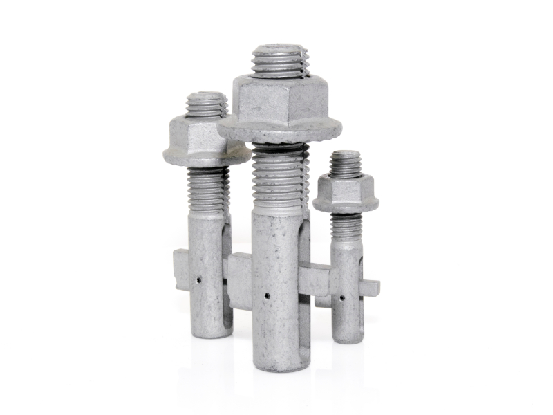
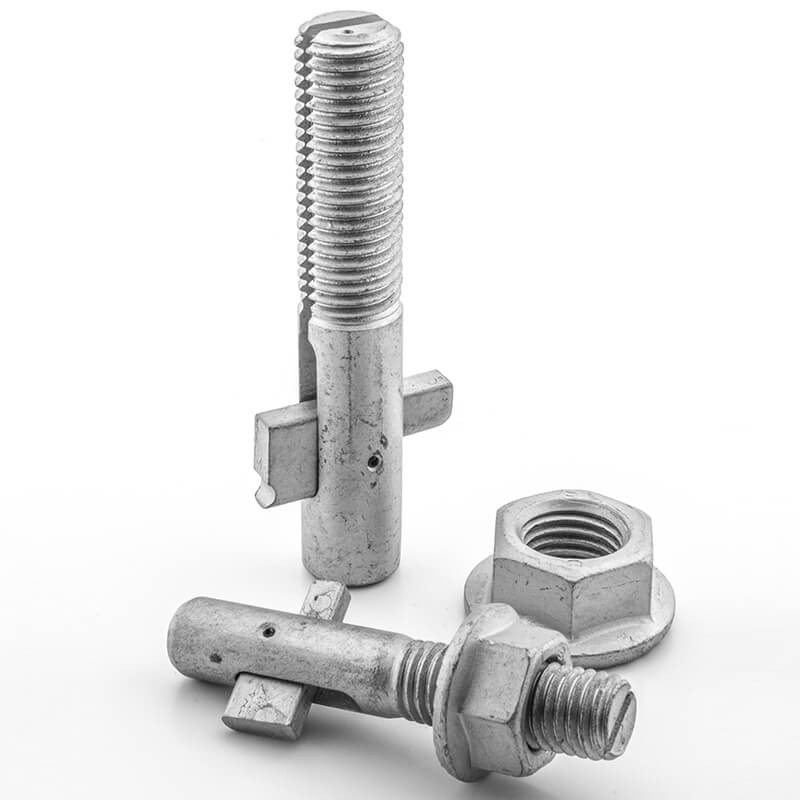
Blind Bolt
Technical Data Explained
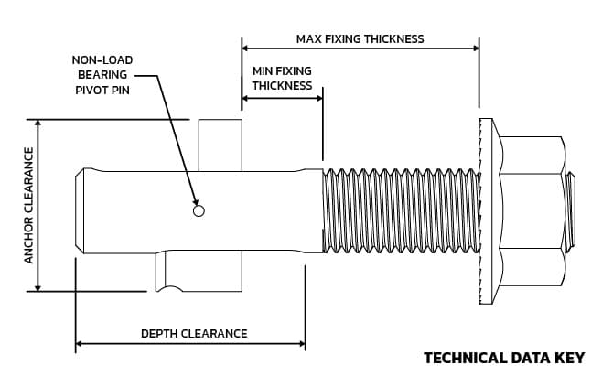
NOTE: All dimensions are in mm unless stated otherwise.
The Blind Bolt Company reserve the right to change these technical details without notice.
Blind Bolt Product Specification - Zinc Flake 1000Hr SSP - Property Class 10.9 |
||||||||||||
| Product Code | Bolt Size | Box Qty |
Hole Diameter |
|
Anchor Clearance |
Depth Clearance |
Minimum Hole Centers |
|||||
| BB0850ZF | M8 x 50 | 50 | 9 | 9 | 24 | 19 | 25 | 20 | ||||
| BB1060ZF | M10 x 60 | 40 | 11 | 10 | 30 | 23 | 30 | 20 | ||||
| BB1095ZF | M10 x 95 | 20 | 11 | 25 | 65 | 23 | 30 | 20 | ||||
| BB10130ZF | M10 x 130 | 20 | 11 | 55 | 100 | 23 | 30 | 20 | ||||
| BB1270ZF | M12 x 70 | 20 | 13 | 12 | 35 | 26 | 35 | 25 | ||||
| GBB30140ZF | M30 x 140* | 5 | 32 | 27 | 60 | 65 | 72 | 75 | ||||
| * We strongly recommend the use of our safety gauges when installing these bolts | ||||||||||||
Blind Bolt Product Specification - Hot Dip Galvanised - Property Class 10.9 |
||||||||||||
| Product Code | Bolt Size | Box Qty |
Hole Diameter |
|
Anchor Clearance |
Depth Clearance |
Minimum Hole Centers |
|||||
| BB1270HDG | M12 x 70 | 20 | 13 | 12 | 35 | 26 | 35 | 25 | ||||
| BB12120HDG | M12 x 120 | 25 | 13 | 30 | 85 | 26 | 35 | 25 | ||||
| BB12180HDG | M12 x 180 | 20 | 13 | 80 | 140 | 26 | 35 | 25 | ||||
| GBB1475HDG | M14 x 75* | 20 | 15 | 14 | 35 | 32 | 38 | 32 | ||||
| GBB14125HDG | M14 x 125* | 20 | 15 | 28 | 82 | 32 | 38 | 32 | ||||
| GBB14185HDG | M14 x 185* | 20 | 15 | 75 | 142 | 32 | 38 | 32 | ||||
| GBB1690HDG | M16 x 90* | 20 | 17 | 13 | 43 | 36 | 43 | 35 | ||||
| GBB16130HDG | M16 x 130* | 15 | 17 | 40 | 75 | 36 | 43 | 35 | ||||
| GBB16180HDG | M16 x 180* | 10 | 17 | 55 | 125 | 36 | 43 | 35 | ||||
| GBB20110HDG | M20 x 110* | 10 | 22 | 21 | 56 | 44 | 56 | 48 | ||||
| GBB20140HDG | M20 x 140* | 8 | 22 | 21 | 86 | 44 | 56 | 48 | ||||
| GBB20180HDG | M20 x 180* | 10 | 22 | 80 | 120 | 44 | 56 | 48 | ||||
| GBB20250HDG | M20 x 250* | 10 | 22 | 130 | 185 | 44 | 56 | 48 | ||||
| GBB24130HDG | M24 x 130* | 5 | 26 | 21 | 62 | 53 | 64 | 60 | ||||
| * We strongly recommend the use of our safety gauges when installing these bolts | ||||||||||||
Important Note
The below tension resistances make no allowance for the deformation or yield of the connected parts. An appropriate design model for connections in hollow sections can be found in Joints in Steel Construction: Simple Connections.
High Tensile Hot Dip Galvanised - Blind Bolt - Design to BS 5950-1 |
||||||
| Diameter |
Tension Capacity |
Shear Capacity |
Shear Capacity Over Slot |
Bearing Capacity |
Recommended Tightening |
|
| Pt (kN) | Ps, thread (kN) | Ps, slot (kN) | S275 Pb, (kN) |
S355 |
Torque (Nm) | |
| M8 | 9.8 | 14.6 | 7.9 | 20.7 | 24.8 | 15 |
| M10 | 14.1 | 23.2 | 15.8 | 27.6 | 33.0 | 24 |
| M12 | 22.4 | 33.7 | 22.0 | 32.2 | 38.5 | 30 |
| M14 | 34.8 | 46.0 | 29.0 | 36.8 | 44.0 | 40 |
| M16 | 38.8 | 62.7 | 43.0 | 46.0 | 55.0 | 50 |
| M20 | 71.4 | 97.9 | 63.4 | 55.2 | 66.0 | 65 |
| M24 | 116.7 | 141.0 | 87.8 | 64.4 | 77.0 | 75 |
| M30 | 174.5 | 224.0 | 137.2 | 80.5 | 96.3 | 85 |
These values are suitable for design to BS 5950-1 and can be used without further reduction for comparison to factored loads. Bearing resistances for different plate thicknesses can be calculated by scaling the values in proportion to the thickness, but should only be used where the distance from the centre line of the hole to the end of the plate is greater than 2d.Combined tension and shear should satisfy the following equation: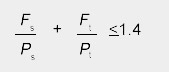 |
||||||
Important Note
The above tension resistances make no allowance for the deformation or yield of the connected parts. An appropriate design model for connections in hollow sections can be found in Joints in Steel Construction: Simple Connections.
High Tensile Hot Dip Galvanised Blind Bolt - Design to BS EN 1993-1-8 |
||||||
| Diameter | Tension Resistance |
Shear Resistance Over Thread |
Shear Resistance Over Slot |
Bearing Resistance in 10mm Plate |
Recommended Tightening Torque |
|
Ft, Rd (kN) |
Fv, Rd thread (kN) |
Fv, Rd Slot (kN) |
S275 Fb, Rd(kN) |
S355 Fb, Rd(kN) |
(Nm) |
|
| M8 | 9.8 | 14.6 | 9.1 | 65.6 | 75.2 | 15 |
| M10 | 14.1 | 23.2 | 19.0 | 82.0 | 94.0 | 24 |
| M12 | 22.4 | 33.7 | 26.4 | 98.4 | 112.8 | 30 |
| M14 | 34.8 | 46.7 | 29.0 | 114.8 | 131.6 | 40 |
| M16 | 38.8 | 62.7 | 49.1 | 131.2 | 150.4 | 50 |
| M20 | 71.4 | 97.9 | 76.1 | 164.0 | 188.0 | 65 |
| M24 | 116.7 | 141.0 | 105.4 | 196.8 | 225.6 | 75 |
| M30 | 174.5 | 224.0 | 164.6 | 246.0 | 282.0 | 85 |
| These are design values for use with BS EN 1993-1-8, and a partial safety factor of γM2 = 1.25 has already been applied. Bearing resistances should be calculated from BS EN 1993-1-8, Table 3.4, taking d as the nominal diameter of the bolt.
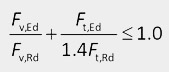
These design resistances are suitable for design to BS EN 1993 and can be compared directly with design loads. The quoted bearing resistances assume k1 = 2.5 and αb = 1.0. For different arrangements the bearing resistance should be calculated using the expression in Table 3.4 of BS EN 1993-1-8, with d as the nominal diameter of the blind bolt. Combined tension and shear should satisfy the following equation:
|
||||||
Important Note
The above tension resistances make no allowance for the deformation or yield of the connected parts. An appropriate design model for connections in hollow sections can be found in Joints in Steel Construction: Simple Connections.
Stainless Steel Blind Bolts Technical Data
Blind Bolt Product Specification Stainless Steel A4-70 |
||||||||||||
| Product Code | Bolt Size |
Box Qty |
Hole Diameter |
|
Anchor Clearance |
Depth Clearance |
Minimum Hole Centers |
|||||
| BB0850A4ASM | M8 x 50 | 50 | 9 | 9 | 24 | 19 | 25 | 20 | ||||
| BB1060A4ASM | M10 x 60 |
40 | 11 | 10 | 30 | 23 | 30 | 20 | ||||
| BB1290A4ASM | M12 x 90 | 20 | 13 | 12 | 55 | 26 | 35 | 25 | ||||
| GBB16100A4ASM* | M16 x 100 |
20 | 17 | 13 | 53 | 36 | 43 | 35 | ||||
| * We strongly recommend the use of our safety gauges when installing these bolts | ||||||||||||
Stainless Steel Blind Bolt Design to BS 5950 |
|||||||
| Diameter | Tension Capacity Pt (kN) |
Shear Capacity Over Thread Ps, thread (kN) |
Shear Capacity Over Slot Ps, slot (kN) |
Bearing Capacity in 10mm Plate |
Recommended Tightening Torque (Nm) |
||
| S275 Pb, (kN) |
S355 Pb, (kN) |
||||||
| M8 | 5.3 | 10.3 | 6.5 | 20.7 | 24.8 | 15 | |
| M10 | 12.7 | 16.2 | 11.1 | 27.6 | 33.0 | 22 | |
| M12 | 21.4 | 23.6 | 15.4 | 32.2 | 38.5 | 28 | |
| M16 | 42.8 | 44.0 | 30.1 | 46.0 | 55.0 | 45 | |
| These capacities are suitable for design to BS 5950-1 and can be compared directly with factored loads. Bearing resistances for different thicknesses can be calculated by scaling the values given in proportion to the thickness, but should only be used when the end distance is greater than 2d.Bolts subject to combined tension and shear should satisfy the following expression: 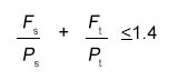 |
|||||||
Important Note
Note that the above tension capacities make no allowance for the deformation or yield of the supporting parts. An appropriate design model for connections in hollow sections can be found in Joints in Steel Construction: Simple Connections.
Stainless Steel Blind Bolt Design to BS EN 1993 |
|||||||
| Diameter | Tension Resistance Ft,Rd (kN) |
Shear Resistance Over Thread Fv,Rd thread(kN) |
Shear Resistance Over Slot Fv,Rd slot (kN) |
Bearing Capacity in 10mm Plate |
Recommended Tightening Torque (Nm) |
||
| S275 Fb,Rd(kN) |
S355 Fb,Rd(kN) |
||||||
| M8 | 5.3 | 12.3 | 7.8 | 65.6 | 75.2 | 15 | |
| M10 | 12.7 | 19.5 | 13.3 | 82.0 | 94.0 | 22 | |
| M12 | 22.0 | 28.3 | 18.4 | 98.4 | 112.8 | 28 | |
| M16 | 42.9 | 52.8 | 36.1 | 131.2 | 150.4 | 45 | |
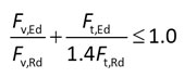
| These design resistances are suitable for design to BS EN 1993 and can be compared directly with design loads. The quoted bearing resistances assume k1 = 2.5 and αb = 1.0. For different arrangements the bearing resistance should be calculated using the expression in Table 3.4 of BS EN 1993-1-8, with d as the nominal diameter of the blind bolt.
Bolts subject to combined tension and shear should satisfy the following expression:
|
|||||||
Important Note
Note that the above tension capacities make no allowance for the deformation or yield of the supporting parts.
Blind Bolt
Testing Data Explained
Due to the unique design of the Blind Bolt there are a number of different fixing combinations possible. Although the tensile strength of the Blind Bolt remains constant, the shear strength of the Blind Bolt can vary depending on the thickness of the material being clamped. These variations are explained below.
Use the menu to see an explanation of the testing criteria found on our technical data sheets. However, if there is anything that you are unsure about please feel free to contact us on the number below or click here to send us an e-mail.
Blind Bolt
Fixing Data Explained
Due to the unique properties of the Blind Bolt there are certain operation criteria that must be met to ensure its successful application. These dimensions are outlined below, please use the menu to the left to isolate each dimension and view a brief description.
However, if there is anything that you are unsure about please feel free to contact us on the number below or click here to send us an e-mail.
Blind Bolt
Fitting Instructions
Installations & Removal Videos
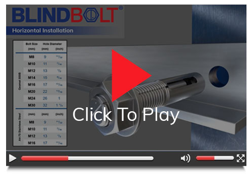
The following videos visually represent both the detailed installation and removal of the Blind Bolt.
Blind Bolt Horizontal
Installation & Removal
Blind Bolt
Horizontal Installation
Blind Bolt
Horizontal Removal

Blind Bolt Downward Installation

Blind Bolt Vertical Removal

Blind Bolt Fitting Instructions (PDF Download)
Blind Bolt
SCI Report