Ultimate Resistances or Safe Working Loads?
Blindbolt UK | 24th August 2022

This article discusses the alternative approaches to structural design in the UK, Europe and North America, the terminology which might be referenced when describing loads on fasteners and how the fasteners resistance (Blind Bolt resistance) tables presented by BlindBolt should be used.
Allowable Stress or Limit State Design Codes
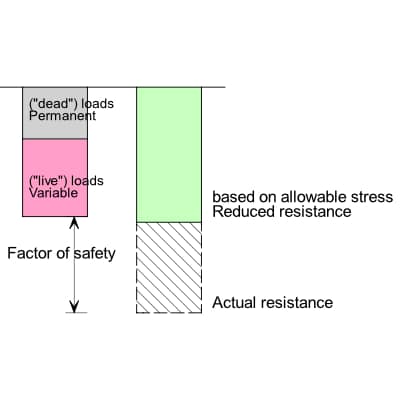
Two approaches to design are in use throughout the world, both designed to give an appropriate factor of safety against failure. An “allowable stress” or “permissible stress” code limits the stress in the material or in the component to a lower level than when the element would actually yield. The reduced resistance is compared to the total load applied. In an allowable stress design code the loads are not amplified (or “factored”) – in modern terminology the loads would be described as the ”characteristic” or “unfactored” loads. The factor of safety is provided by the difference between the applied characteristic loads and the (reduced) resistance. In the UK, BS 449 was used for the design of steelwork until 1985 and is a permissible stress code. The permissible stress to be used when calculating the resistance of elements is specified in the standard.
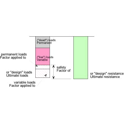
BS 5950, which was introduced in 1985, and BS EN 1993-1-1, which was introduced in 2005 are both limit state design codes. In limit state design, the characteristic loads are amplified by partial factors to produce design loads – often known as ultimate loads. Ultimate loads are significantly higher than the loads expected in reality. The ultimate loads are compared to a calculated resistance, but unlike a permissible stress code, the resistance is based on the actual failure strength of the element. Although the design resistance is calculated on the actual material strength, there may be a reduction to allow for uncertainty in material properties or structural behaviour. The resistance calculated after allowing for the uncertainty is known as the “design resistance” (or “ultimate resistance”).
The two approaches are illustrated conceptually below.
The advantage of a limit state design is that different factors can be applied to different types of load, reflecting the variability of the load. For example, permanent actions (or “dead loads”) can generally be calculated with precision. In contrast, there is less accuracy with variable actions (or “live loads”) such as wind loads, so these types of load attract a higher factor. When multiple variable actions are considered, such as concurrent snow loading and wind load, the reduced probability of both load types being at their maximum values can be reflected in reduced factors. In contrast, an allowable stress design approach involves the simple summation of all types of load.
“Safe Load” Values
Historically, some fixings used in construction may have had resistances described as “safe loads”. Generally, these loads were the actual resistance of the fastener (either calculated or tested), divided by some factor, which might be 2.5 or even larger. The manufacturer’s literature might advise what factor had been applied. As will be seen from the previous discussion, such “safe load” resistances are not compatible with either a permissible stress code or a limit state code.
BlindBolt Resistances for Use with BS 5950 And BS EN 1993
In the UK, any design code may be followed, so BS 449, BS 5950 and the Eurocode are all used, though BS 449 is no longer common.
The resistances provided by BlindBolt are all ultimate resistances, intended for use with BS 5950 or the Eurocode. Once the ultimate load on a BlindBolt has been calculated, in tension, in shear or in combination, the ultimate loads should be compared directly with the ultimate resistances and an appropriate fixing specified.
If the structural design is to BS 449 or some other allowable stress design code, the designer will calculate a characteristic value of the load on the fastener, due to the summation of the applied actions. In this situation, the simple and conservative approach is to multiply that calculated characteristic force on the fastener to determine an ultimate load. The maximum factor is 1.6 according to BS 5950 and 1.5 according to the Eurocode, so to use either of these values will be safe. The use of the Eurocode factor of 1.5 is recommended.
US Design Codes
Historically, North American design followed the permissible stress approach. More recently permissible stress design and limit state design have both been available for design and both appear in the same standard, AISC 360. The two approaches are known as allowable stress design (ASD) and load and resistance factor design (LRFD).
As both design approaches are in common use in North America, BlindBolt provide tables of the design strength (for LRFD) and allowable strength (for ASD). The LRFD resistance is 1.5 times higher than the ASD resistance, which is a similar factor to that found in the UK when comparing BS 449 and limit state standards.
Find Your BlindBolt Today By...
... checking out our detailed guide to Blind Bolts by clicking here. You can also find out more about blind bolts by speaking to our expert team today on +44 (01299) 272 955 by emailing enquiries@blindbolt.co.uk.

